File:Jet engine numbered.svg

此SVG文件的PNG预览的大小:800 × 334像素。 其他分辨率:320 × 134像素 | 640 × 267像素 | 1,024 × 428像素 | 1,280 × 535像素 | 2,560 × 1,069像素 | 910 × 380像素。
原始文件 (SVG文件,尺寸为910 × 380像素,文件大小:447 KB)
摘要
| 描述 |
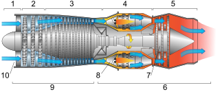
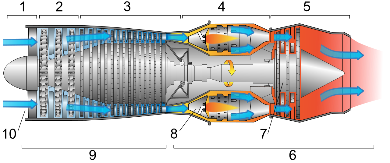
Deutsch: Schemazeichnung eines typischen Gasturbinen-Triebwerks. Luft wird durch die Gebläsesschaufeln im Verdichterabschnitt komprimiert, wenn sie in die Turbine eintritt. Sie wird mit Kraftstoff gemischt und im Verbrennungsabschnitt verbrannt. Die heißen Abgase entwickeln Schub nach vorne und drehen die Turbinenschaufeln und damit die Gebläseschaufeln im Verdichterabschnitt.
English: Diagram of a typical gas turbine jet engine. Air is compressed by the fan blades as it enters the engine, and it is mixed and burned with fuel in the combustion section. The hot exhaust gases provide forward thrust and turn the turbines which drive the compressor fan blades.
Français : Schéma montrant un turboréacteur d'avion typique (simple flux, simple corps). L'air est comprimé par les pales en entrant dans le réacteur, puis est mélangé avec le carburant qui brule dans la chambre de combustion. Les gaz d'échappement génèrent une forte réaction vers l'avant, et font également tourner les turbines qui actionnent les pales de compression.
Español: Esquema de un motor estándar a reacción. El aire es comprimido por las palas del ventilador, para ser mezclado con el carburante y explosionado en la cámara de compresión. La salida de los gases realiza un fuerte empuje hacia delante y hacen girar las turbinas que accionan las palas de compresión.
Català: Esquema d'un motor estàndard a reacció. L'aire d'entrada es comprimit per les pales o àleps del ventilador, per ser seguidament barrejat amb el combustible a la cambra de combustió. La sortida dels gasos provoca l'impuls i fa girar les turbines, les quals mouen les pales de compressió.
Română: Schema unei turbine cu gaze. Aerul introdus este comprimat de paletele compresorului, după care intră în camera de ardere, unde este introdus combustibil. Amestecul este aprins, iar gazele de ardere se destind în turbină, efectuând lucru mecanic. În imagine sunt specificate următoarele părţi componente:
Русский: Схема турбореактивного двигателя. Воздух сжимается лопастями компрессора, смешивается с топливом, смесь поступает в камеру сгорания. Горячие выхлопные газы обеспечивают движение вперёд и приводят в действие компрессор.
Polski: Schemat jednoprzepływowego silnika turboodrzutowego. Powietrze pod ciśnieniem wtłaczane jest przez sprężarkę do komory spalania gdzie dostarczane jest paliwo i zachodzi proces spalania. Gorące spaliny napędzają turbinę połączona wałem ze sprężarką.
Tiếng Việt: Sơ đồ của một động cơ turbin phản lực. Không khí được nén từ các quạt khi nó đi vào động cơ, và nó được trộn và bị đốt với nhiên nhiệu trong buồng đốt.
中文:一个典型的燃气涡轮喷气发动机图解。上面流程标识为:
|
||
| 日期 | (UTC) | ||
| 来源 | 自己的作品, vector version of en:Image:FAA-8083-3A Fig 14-1.PNG which comes from an FAA handbook | ||
| 作者 | Jeff Dahl | ||
| 其他版本 |
[]
|
||
| SVG开发 |

.PNG)

|

English: Diagram of a typical gas turbine jet engine. 其他语言:
Afrikaans: Diagram van 'n tipiese gasturbine stralerenjin Alemannisch: Äs Diagram vom a nä Strautriebwärch Asturianu: Cadarma d'un reautor. Bosanski: Dijagram tipičnog avionskog benzinskog motora. Čeština: Schematické znázornění proudového motoru Deutsch: Diagramm eines Strahltriebwerks English: Diagram of a typical gas turbine jet engine. Español: Diagrama de un reactor. Euskara: Erreakzio-motore baten diagrama. Français : Schéma montrant un turboréacteur d'avion typique Íslenska: Skýringarmynd sem sýnir dæmigerðan þotuhreyfil. Italiano: Schema di un motore a getto. Lietuvių: Tipiška dujų turbinos reaktyvinio variklio diagrama. Magyar: Gázturbinás sugárhajtómű felépítése Nederlands: diagram van een tunnelschroefturbine Português: Diagrama esquemático de uma típica turbina a gás. Română: Schemă numerotată a celei mai comune turbinei cu gaze folosită în aviație. Svenska: Schematisk bild av en turbinjetmotor. Беларуская: Схема газавай турбіны рэактыўнага рухавіка Русский: Схема турбореактивного двигателя. Српски / srpski: Дијаграм типичне авионске бензинске турбине (мотора). 한국어: 전형적인 가스 터빈 제트 엔진의 다이어그램. 中文: 一个典型的燃气涡轮喷气发动机图解 |
This image was selected as picture of the day on Vietnamese Wikipedia.
|
许可协议
Jeff Dahl,本作品著作权人,特此采用以下许可协议发表本作品:

|
已授权您依据自由软件基金会发行的无固定段落及封面封底文字(Invariant Sections, Front-Cover Texts, and Back-Cover Texts)的GNU自由文件许可协议1.2版或任意后续版本的条款,复制、传播和/或修改本文件。该协议的副本请见“GNU Free Documentation License”。 |
This file is licensed under the Creative Commons Attribution-Share Alike 4.0 International, 3.0 Unported, 2.5 Generic, 2.0 Generic and 1.0 Generic license.
署名: Jeff Dahl
- 您可以自由地:
- 共享 – 复制、发行并传播本作品
- 修改 – 改编作品
- 惟须遵守下列条件:
- 署名 – 您必须对作品进行署名,提供授权条款的链接,并说明是否对原始内容进行了更改。您可以用任何合理的方式来署名,但不得以任何方式表明许可人认可您或您的使用。
- 相同方式共享 – 如果您再混合、转换或者基于本作品进行创作,您必须以与原先许可协议相同或相兼容的许可协议分发您贡献的作品。
您可以选择您需要的许可协议。
| 註解 | 該圖片含有註解:在維基媒體共享資源上查看註解 |
文件历史
点击某个日期/时间查看对应时刻的文件。
| 日期/时间 | 缩略图 | 大小 | 用户 | 备注 | |
|---|---|---|---|---|---|
| 当前 | 2008年1月8日 (二) 04:25 | | 910 × 380(447 KB) | Jeff Dahl | Label fixes |
| 2008年1月7日 (一) 18:45 |  | 910 × 380(444 KB) | Jeff Dahl | stroke to path | |
| 2008年1月7日 (一) 18:43 |  | 910 × 380(444 KB) | Jeff Dahl | Bracket fixes | |
| 2008年1月7日 (一) 18:40 |  | 910 × 380(443 KB) | Jeff Dahl | Bracket fixes | |
| 2008年1月7日 (一) 18:37 |  | 910 × 380(443 KB) | Jeff Dahl | bracket fixes | |
| 2008年1月7日 (一) 18:32 |  | 910 × 380(443 KB) | Jeff Dahl | rm whitespace | |
| 2008年1月7日 (一) 07:09 | 1,000 × 400(444 KB) | Jeff Dahl | {{Inkscape}} {{Information |Description={{en|Diagram of a typical gas turbine jet engine.}} |Source=self-made |Date=~~~~~ |Author= Jeff Dahl |Permission= |other_versions=100px }} |
文件用途
全域文件用途
以下其他wiki使用此文件:
- ar.wikipedia.org上的用途
- az.wikipedia.org上的用途
- ba.wikipedia.org上的用途
- be.wikipedia.org上的用途
- bn.wikipedia.org上的用途
- ca.wikipedia.org上的用途
- crh.wikipedia.org上的用途
- cv.wikipedia.org上的用途
- de.wikipedia.org上的用途
- en.wikipedia.org上的用途
- es.wikipedia.org上的用途
- eu.wikipedia.org上的用途
- hu.wikipedia.org上的用途
- hy.wikipedia.org上的用途
- it.wikipedia.org上的用途
- ko.wikipedia.org上的用途
- lbe.wikipedia.org上的用途
- mg.wikipedia.org上的用途
- nl.wikipedia.org上的用途
- nl.wiktionary.org上的用途
- os.wikipedia.org上的用途
- outreach.wikimedia.org上的用途
- pl.wikipedia.org上的用途
- pt.wikipedia.org上的用途
- ru.wikipedia.org上的用途
- ru.wikinews.org上的用途
查看本文件的更多全域用途。